There are times in life when things are rather subjective or can change from time to time, one such scenario could be while dining. The waiter reaches over your salad with their pepper grinder hovering and says, “Just Say When” implying you tell them when to stop grinding pepper on top of your salad.

How much pepper you choose to add to your salad is up to you. In contrast, when injecting a mold with resin there is a set volume the mold can accept. Overfilling or underfilling the mold can have impacts on part quality, production performance, and the health of the molding operation, let alone lowering profits and wasting money.
When reviewing many closed molders’ general practices it revealed that the volume of resin injected into their molds is inconsistent. The impact of that inconsistency is driving excessive cost and reducing tool life.
This article addresses both the factors that prevent the RTM/LRTM or Vacuum Infusion mold from consistently filling and the solution to gain control over this vital element of the closed molding injection process.
First, we’ll consider the methods used to halt the resin injection once the mold is filled. Then we’ll review the variables that are driving the apparent need to change the resin fill volume on the molding floor.
RTM, LRTM, & Vacuum Infusion (VARTM) Closed Molding
When it comes to the critical production step of filling a mold with resin, there must be a predetermined control on the volume of resin that is injected into the mold. There shouldn’t be a “variance” in the injection volume between molding cycles. Unlike pepper on a salad, the time to say “when” for total resin injection volume is set by the closed cavity volume and not subject to change.
Resin Waste Goes Back to the Historical Beginnings

Too often “when” to stop the injection on the molding floor is when the mold is overfilled with resin and is witnessed at the vent, causing resin waste, mold stress, excessively thick parts, and post mold rework.
Before the 1980s Operators Kept Count
Back in the early 1980s and prior, the composite industry relied on the operator to know how many “strokes” of resin were to be pumped into the mold by “listening” to the pump and counting strokes as the mold filled, assuming they did not lose count, the operator would halt or stops the injection at the moment the mold was filled.
The Mid-1980s Brought the Stroke Counter
The stroke counter keeps track of strokes throughout an injection and halts the injection when the predetermined count is reached.
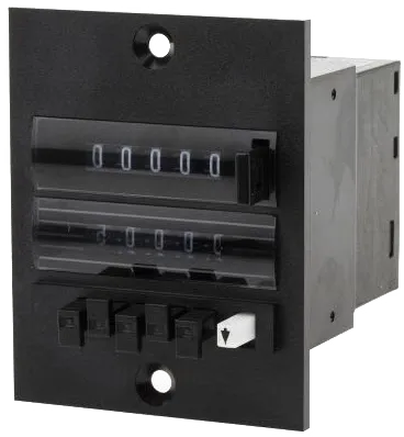
Each time a different mold is presented to the injection system, the stroke counter must manually be reset from the previous injection and updated with the predetermined count to match the current mold.
This is done by an operator who often refers to a handwritten value scribbled down on the mold near the injection point, or sometimes in an injection journal/notepad. Though the stroke counter is an upgrade from the operator listening and keeping count, it still unnecessarily opens the injection process to human error and is considered obsolete with today’s simplified technology.
The 1990s and the Mold Protection Guard
The 1990s brought the Mold Protection Guard or MPG, which worked in unison with a pump speed setting—similar to how the count is preset within the stroke counter. The motivation for the MPG was influenced by the higher injection pressures used during the 90s within the RTM process.
The MPG acts as a regulator for the resin pump, restricting airflow to the pump when the pressure exceeded the set limit. Though the MPG is a pressure control, it began exposing the need for what is now understood as flow control.
Though the MPG provided a solution for the higher pressure environments of RTM it’s inadequate for today’s lighter molding process, such as LRTM and VARTM.
2020 Modern-Day Solution is RFID Technology
Today’s advancements in technology have brought many improvements to the composite industry, one of which is radio-frequency identification or RFID as it’s more commonly known as.
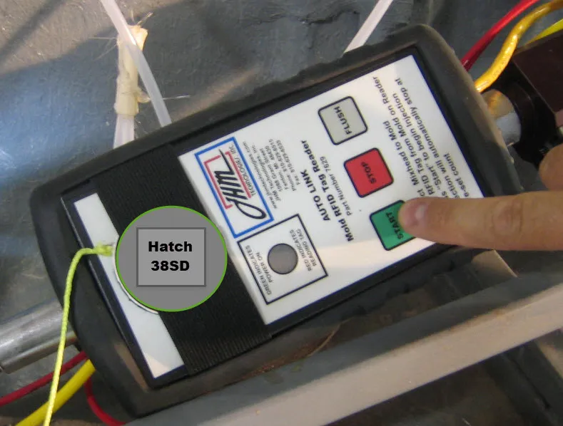
Using unique RFID tags that are directly attached and assigned to each mold, a modern meter mix injection system has enough insight and understanding to allow an operator to start the injection with a single button press. Massively reducing and removing human operator error.
Each RFID tag is linked with a mold and backed by a predetermined recipe within the injection system. The operator uses the RFID reader, which is normally attached to the injection wand, by setting the tag on the reader and pressing start. The injection machine knows exactly which recipe to use and ultimately how many “strokes” to put into the mold. However precise control over stroke count is only the beginning when using recipes.
Mold Link by JHM Technologies, Inc. is an RFID tag solution for modern-day production environments and is available on the Infuser line of injection systems. Mold Link has been leading innovation with RFID technology in the composite industry, truly opening the doors to a precise, repeatable, and predictable production process in a cost-effective way.
Stroke Counter Compared to Mold Link
Today, Infusatrol’s Mold Link technology is a far superior method of controlling resin volume in each mold when compared to the earlier alternatives of using a manual stroke counter.

Several steps are involved for the operator to program the stroke counter which is prone to human error and suffers from no means to confirm process compliance on the floor.
Each mold count, or recipe, is held in the “Infusatrol” Infuser machine memory with no need for the operator to program each digit manually.
Each time the Injection System is connected to a mold, the Mold Link tag attached to that mold is placed on the Mold Link reader and then the operator simply presses the “start” button which instantly sets the counts to fill the mold automatically without concern of human error. This takes a huge weight of responsibility off the operators.
Reliable and repeatable production is simple with Mold Link
Coming to Terms With Injection Process Variables
How do you Determine the Stroke Count for a Mold?
The stroke count should be a factor of the total mold cavity volume less than the volume of the fiber. Using a common fiber load as an example: If the composite laminate is to have 30% by weight fiber, then the fiber “volume” would be ~17% of the mold cavity volume leaving ~83% plus any injection feed line volume to divide by 100 CC to calculate the needed stroke counts for the mold injection. This value shall then be the set volume needed for the mold fill.
Stroke Counts Variances
Often, the number programmed manually into the stroke counter is handwritten on the top side of each mold for the operator reference. Molders with a documented process will have a stroke count documented in their written process, yet in practice, the documented number of counts may well not be the amount injected currently on the molding floor.
The reason for the variance in pump stroke counts is an important topic not professionally managed in today’s closed molding processes. However, the volume variances have a direct impact on the molded part quality, mold life/maintenance, and true production throughput.
Understanding Variances in Stroke Count for a Mold
Injection volume for a mold should not change unless the fiber load or the mold has physically changed. The variance is a lack of process controls!
Let us peek behind the curtain into a real-world production example of closed molding today.
When visiting an RTM, LRTM, or VARTM closed molding plant you will most often see numbers written on the backside of the molds indicating counts for resin injection volume. Those counts can be accompanied by other counts that had been scribbled out some time ago, usually by a previous operator.
What this shows is the amount of resin pumped into the mold has changed as molding issues appear on the molding floor. As the issue(s) are worked through, the operator will change the stroke count value, in most cases adding additional strokes of resin volume.
The White Elephant in the Room That Most Molders Ignore
If the mold has not been modified in size, nor fiber volume changed, then how can the “volume” of resin needed to fill the mold change? The part cavity volume does not change, so unless fiber volume changes, the precise same amount of resin to fill the mold from part 1 to part 1000 or more should be a constant—it shouldn’t change.
What are the concerns if the stroke counts are changed?
-
Resin Cost: The stroke of a professional injection systems count volume is ~ 1/4 pound of resin (100 CCs). For every 4 counts over the actual needed amount to fill the mold the waste is nearly a pound of resin which can cost from $1.00 to $2.00 per pound. It is, however, not too uncommon to find molds that are overfilled by far more than 4 counts. The waste of 1 to 2 or more pounds of resin per part becomes a substantial cost very quickly.
A recent survey of several Molder’s asking: What is your resin inventory variance when audited?
The responses were normally that variance is far greater than 17% higher than BOM usage. Which is to say, it takes >117% of the planned bill of materials for the resin to fill the molds. Highlighting at minimum, molders are paying >17% more for their resin than needed due to pumping in more resin that the mold can hold.
-
Mold Life: If you stop and think about it, if the mold cavity volume were filled with the correct dry fiber, and then as an example; to fill the remaining cavity (part area) were say 10 pounds of resin. Yet, the operator pumped in an additional 1.7 pounds of resin, what happened in the mold part cavity? The mold was forced to increase in cavity volume and thus the only way to do so is to open the mold and make a thicker part. This forces the mold open which puts heavy stress on the mold and is often witnessed in cracking of the mold surface.
-
Part Post Mold Rework: When the mold is forced open, we are faced with the added cost found in resin waste and mold life reduction/maintenance, we are also faced with far more post-mold rework of the parts produced.
Controlling Injection Pressure
All immediately agree that injecting resin into a closed mold at “too high” of pressure is going to force the mold open. Yet, what is not well understood is how little pressure is needed to open the mold. Many have put trust in the injection equipment to have the “Mold Protection Guard” or MPG. Not realizing the MPG was designed back in the early 1990s when the typical injection was a higher pressure than what is common in today’s light structure tooling.
The MPG is an extremely limited form of “flow control” yet as a means of simple explanation, has been introduced as a “pressure control”.

MPG function is like holding down on the gas pedal while “pumping” the brake to control the car’s speed.
To better illustrate how the MPG worked, it can be likened to pressing down on the gas and then trying to tap the brake at the same time in an attempt to control the speed of the car. While the concept would have some level of control it is easy to see that adjusting the pressure on the accelerator—gas pedal in this analogy—is a much more practical and elegant means to control the car speed.
Deeper Insight Into Injection Pressure
Professional Injection systems use an 11 to 1 power ratio between the compressed air pressure powering the powerhead air motor and the actual resin pressure exiting the resin fluid section of the pump with lighter duty pumps use a 7 to 1 ratio.
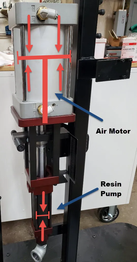
The resin pump ratio is the factor of the air motor piston diameter compared to the resin pump rod diameter. The reciprocating action of the piston pump is driven by the air motor piston connected directly to the resin pump rod, the area of the air motor piston is either 7 or 11 times larger than the resin pump rod. This factor then amplifies the resin pump output pressure by the factor of the difference.
The resin pump displaces resin in both the up and down stroke as the air motor reciprocates.
Note: The shorter the pump stroke the more often the pump needs to reverse direction, it is the moment at the top and bottom of the stroke where the potential to affect the “resin and catalyst” mix ratio is most vulnerable. The equipment manufacturers will shorten the pump stroke to reduce their cost in manufacturing the pump, yet at the cost of the molder.
Referring to the resin pump power ratio, and using the lower 7 to 1 example, should the resin pump be fed with 10 psi of air pressure, the static resin delivery pressure would be 70 psi.
Considering a lightweight LRTM mold upper for instance, such as those built today weigh 10 pounds, or less, per square foot of mold area.
If we look at just one square foot of mold and consider that there are 144 square inches within that 12″ x 12″ area. If we were to apply only 10 psi resin pressure to the mold in that 1 sq/ft area we would have a lifting force equal to 1,440 pounds. Realizing the resin pump with as little as 10 psi air supply pressure amplifies the resin static pressure to 70 psi we can easily see the mold has no means to remain closed, even with the mold flange having a vacuum area and initially the mold cavity having a regulated vacuum, still the forces possible in the resin delivery easily outweigh the clamping forces.
With just 10 psi of resin injection pressure, we can lift the mold upper 144 times over. This fact is usually overlooked when determining how to control the injection process.
Understanding how little injection pressure is required to open a mold, we now start to have insights into the primary cause of variance in mold fill volume. Yet, it is still common in the industry to allow the operator to simply add more strokes. Resulting in wasted resin, unneeded mold stress and wear, and post-mold rework of parts.
The Rise and Fall of Zero Injection Pressure (ZIP)
In 2001, JHM Technologies, Inc. began controlling the injection process on the foundation of injection “pressure” alone. Pressure sensors were installed within the mold cavity. This feature opened the door to confirm the vacuum level in the mold cavity for processes such as LRTM, confirmed the vacuum cavity level before injection, and also provided a “set point” of maximum dynamic resin pressure to which the injection system could react to. Some equipment manufacturers still follow this path having been motivated by the Zero Injection Pressure (ZIP) technology.

A new industry acronym was created with ZIP RTM technology, which represents the process of maintaining the injection pressure below “gain” to the outer atmospheric pressure, working to hold the mold cavity closed during the injection process. The leap in additional process control with ZIP technology over the MPG technology was immediately realized and patent applications were granted in Europe while pending in the USA as acceptance of the process grew.
The Composite Fabricator Magazine featured the ZIP molding technology on the front cover of their March 2003 edition. This feature article was to highlight the advancements of JHM Technologies, Inc. patented Zero Injection Pressure gain to atmosphere process (ZIP RTM). From 2001 to 2004 JHM supplied many different molding applications with the ZIP technology in which the pressure within the cavity was to be maintained below the external clamping atmospheric force.
Ultimately the ZIP technology was abandoned as we realized it’s not possible to prevent the mold from opening during the injection process using pressure control alone, especially as we worked to push the envelope on the speed of injection.
What was learned during the ZIP phase also shed light on a reason using MPG alone wasn’t enough for controlling the mold closure during the injection.
There comes a very fine point when the mold begins to open, it in effect “pops” this is the point in which even if the injection process is paused, the upper often cannot settle back down on the Z plane mold stops. Once this happens the mold cavity has opened increasing the part thickness and requirement for the additional resin to fill the mold, as well as the loss of control of the resin flow path which resulted in air entrapments or dry spots found in the part when the mold was opened.
Control Flow Rate and use Pressure as a Governor, Infusatrol
Using the knowledge learned from working with pressure alone as the control, we reflected on other injection processes especially that of thermoplastic injection in which the flow rate is the focus of the process control.
The Infusatrol injection control software was developed with proprietary algorithms to manage the air over hydraulic resin pressure provided by the injection system. This allows accurate control of the injection flow rate and monitoring the injection pressure in real-time. This state-of-the-art control has been working to provide users of the Infuser series of injection systems with an extremely competitive advantage over molders attempting to blindly control their process through the belief and faith in the MPG alone.
With Infusatrol, should the injection pressure limit be exceeded, the Infuser will momentarily stop and automatically reset the flow rate setting to a lower value and then ramp up to the new lowered flow rate. The purpose is again to hold on to a constant dynamic flow rate yet react to the pressure exceeding a set limit.
Using Infusatrol the upper mold half may be so light it is a nylon or silicone rubber film and no rigid structure at all and control over the flow rate is still available.
The Progression to a Simpler, Repeatable, and Modern Solution
The MPG sensor is accompanied by a second operator setting for “pump speed” control, which is simply the regulated air pressure feeding the resin pump. The first limitation of the MPG sensor is the fact it requires several PSI in resin pressure to push the diaphragm up and to send a signal to choke off the air supply to the resin pump air motor. Then once it does trigger, and the air supply to the resin pump is restricted, the resin pump slows, yet the same pump speed setting remains. Again, like holding the gas pedal down as it were. As the resin pressure in the feed line to the mold drops from the resin pump restriction, the MPG diaphragm returns to allow the pump to be fed with air pressure again, yet the “pump speed” regulator remains constant so again the pressure builds in the mold.
The trouble is, that for the same reason the ZIP technology was abandoned, the mold often has “popped” and actually the back pressure from the resin feed drops as the mold opens and the added cavity opening allows the resin to flow easier into the mold, while simultaneously losing control of the resin flow front leading edge and resin flowing in the path(s) of least resistance. At this point, the MPG is doing nothing and the pump is flowing at the pump speed setting.
This phenomenon can be witnessed using the Infusatrol controls, in real-time the actual flow rate and the actual resin feed pressure is displayed on the control screen. As the mold continues to fill, the actual resin pressure steadily rises, as the flow rate is held at the predetermined set point.
If however, the flow rate setting is too high, then resin pressure will continue to rise, should the pressure exceed the “upper limit” setting for pressure, then Infusatrol will halt the resin pump momentarily, reset the flow rate setting to a lower value and then begin flowing at the lower pump speed setting. However, if the upper limit setting for resin pressure is set too high and allows the resin to be pumped into the mold at the same flow rate setting, the “actual” resin pressure will drop. This indicates the mold has been opened making it easier for the resin to flow into the expanded mold.
This insight allows for the maximum pressure limit to be set low enough to prevent the mold from opening and yet allows for the flow rate to be maximized to allow filling the mold, without opening, at the fastest rate possible. To take this control to a greater level, the Infusatrol can have multiple “steps” during injection which trigger at different stroke counts during the fill, as the mold fills, the flow rate and pressure limit can have a different setting. This allows for rapid injection at the beginning and to progressively slow the flow rate as the mold continues to fill.
Through the combination of Mold Link, automated flow rate, and pressure control provided by Infusatrol, today’s molders are operating with modern technology leaving behind the obsolete 1980 and 1990s level of control as critically needed today in the competitive global market that we live in.
Simplify Your Process Today
Take control and simplify your injection process today with today’s industry leading technology. Remove operator error and improve production throughput, automate reporting and reduce waste, drastically reduce post-mold rework, all while extending the life of your molds.
All of those features and more are available with Infusatrol on the Infuser series injection systems. The Infuser injection system is competitively priced against the competitors while being the only injection system which pays for itself in reduced material costs, mold maintenance, and post-mold part rework.
JHM Technologies, Inc. has a full line of meter mix injection systems for polyesters, vinyl esters, epoxies, and urethanes. Systems ranging from the industrial Flow Master to the PRG Servo used in the aerospace applications with 2 component epoxies at 300 degrees held within a 1% mix ratio all while taking advantage of the Infusatrol injection software.
JHM Technologies, Inc. is the oldest manufacturer in North America for RTM injection systems. The product line was built specifically for the advancement and to serve the RTM molders worldwide.
To simplify and gain control of your molding process visit www.rtmcomposites.com/contact or call +1 810-629-6515 and speak with the team who has over 40 years of hands on molding experience.